

It is possible to align the burrs in a single grinder with enough time spent selecting parts and making adjustments. The harder job is getting a consistent result across a production run, without spending hours on every unit.
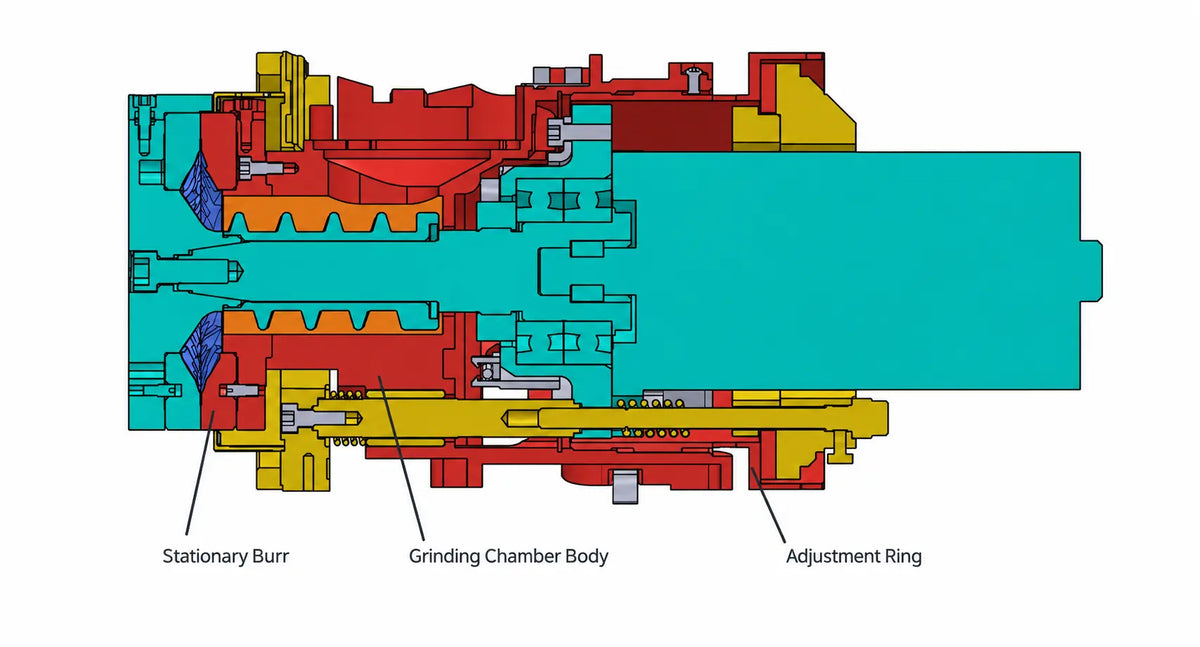
The burrs do not mount directly to each other. Their relative position depends on the spindle, bearings, housing, carriers and the interfaces between them. Machining each part accurately matters, but small deviations can still add up after assembly. Motto80 addresses that problem in three places: at the rotating assembly, at the burr alignment mechanism and at the guide that moves with the grind setting.
Why part tolerances are only part of the story
Imagine five interfaces that each contribute an equivalent 5 μm deviation at the burr edge, all in the same direction. The combined deviation could reach 25 μm. That is a simplified example, not a Motto80 measurement. In an actual assembly, the direction and geometry of each error also matter, so the numbers on part drawings cannot simply be added to predict the final burr position.
One response is to tighten tolerances across more components, match parts selectively or rework assemblies that fall outside the target. Those approaches can improve the result, but the time and cost recur for every batch. We machine critical Motto80 parts to tight tolerances and provide an adjustment where assembly can introduce a correctable tilt. We then measure the assembled result.
First, establish an accurate rotating assembly
Before adjusting the stationary burr, we need to know how the rotating burr mounting face behaves through a full revolution. If that face moves axially as the spindle turns, adjusting the stationary side cannot remove the movement.
Motto80 uses a 15 mm stainless steel spindle supported by two angular contact bearings. Controlled fits and a locking arrangement establish the support structure. Once that assembly is complete, a standardized fixture holds the bearing housing while the spindle turns. We measure axial variation at a specified point on the burr mounting face over one revolution. The factory acceptance limit for this face runout is 20 μm (0.020 mm).
We inspect the face that will actually support the burr, rather than the bare spindle alone. That check includes the combined effects of the spindle, bearings and burr carrier connection before the assembly moves into the grinder.

Then, align the burrs after assembly
An accurate rotating assembly does not guarantee that the two burrs will be parallel once the grinder is assembled. Other components and mating surfaces sit between the rotating and stationary burrs. A small deviation at one of those interfaces can tilt the stationary side.

Three adjustment screws let us change the orientation of the supporting structure. During factory assembly, an electronically controlled fixture assists this alignment step. The principle is familiar to anyone who has used thin shims to align grinder burrs, but the adjustment is built into the Motto80 structure and paired with dedicated production tooling.
If an interface introduces a small carrier tilt, the three point mechanism can correct it after assembly, provided the tilt is within its adjustment range. It cannot correct spindle runout, and it does not remove the need to machine the spindle, bearing fits and guide components accurately. It deals with the relative tilt that appears when multiple parts come together.

Why the finished grinder has a 25 μm limit
Under specific conditions evaluated by our engineering team, the alignment step has demonstrated a best case capability of approximately half the spindle accuracy figure. For example, a 20 μm spindle measurement corresponds to approximately 10 μm of alignment capability under those conditions. That 10 μm figure describes the adjustment step. It is not the overall accuracy specification for a finished grinder.
A production limit also has to account for residual assembly errors, inspection, adjustment time and the cost of reaching and verifying tighter results. Taking those factors together, we set a final factory acceptance limit of 25 μm for burr parallelism.
This number refers to variation in the burr gap, not a maximum burr spacing of 25 μm. At the same reference radius, for example, a smallest measured gap of 200 μm and a largest of 225 μm would give a 25 μm variation. The purpose of the limit is to set a result that finished units can meet consistently, without depending on unusually favorable parts or lengthy individual adjustment.
Keep that alignment as the setting changes
The stationary burr carrier moves when the grind setting changes. If it tilts during that movement, an alignment achieved at one setting will not hold across the operating range.
Three sliding guide pins control the carrier's movement. Their outer surfaces are centerless ground, and the mating holes are finished by boring to control the fit. The pins help preserve the carrier's orientation as burr spacing changes. The spindle controls rotational accuracy, the three point adjustment sets the relative burr position, and the guide pins help maintain it as the carrier moves. Each addresses a different source of error.
What alignment does and does not measure
The 20 μm mounting face runout limit and the 25 μm final burr parallelism limit are separate factory checks. Neither should be substituted for the other. The approximately 10 μm figure is a best case result for the alignment step under specific conditions, not an acceptance limit for the complete grinder.
There is also a separate question about the burrs themselves. Their mating surfaces and cutting profiles can have small variations. A mechanical alignment figure does not mean that every point on the cutting surfaces has exactly the same gap. The process described here controls how the two burr assemblies sit relative to each other; the burr manufacturing process governs the geometry of the burr surfaces.
For us, precision in production means measuring the rotating assembly, correcting alignment after assembly and checking the finished grinder against a defined limit. That is how we work toward a repeatable result while keeping machining requirements, adjustment time and production cost under control.
Share:
Understanding the Motto80's grinding sound: why bean feed rate matters